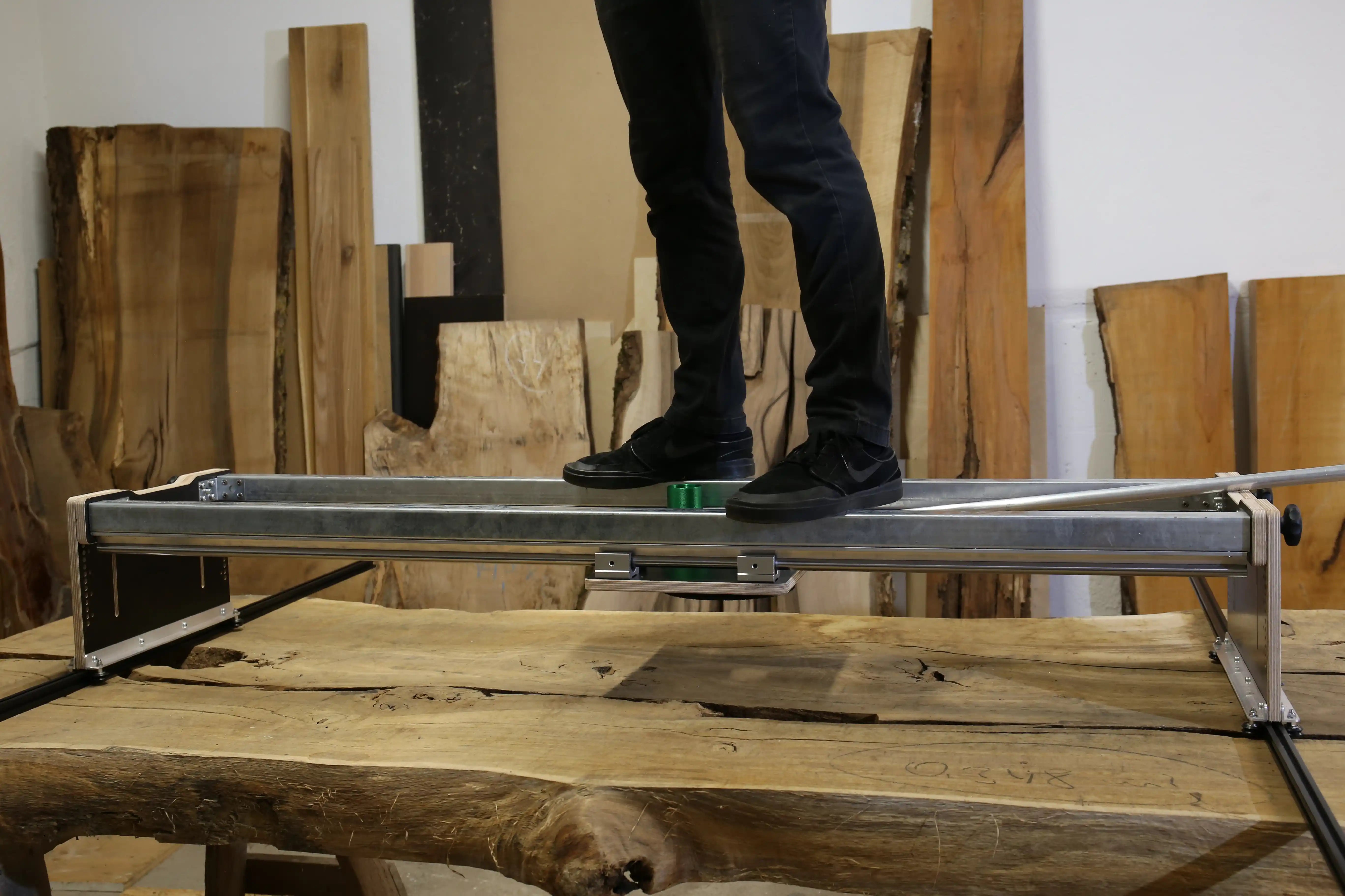
When flattening large wood slabs, the router isn't the only thing that matters. The guide has to be stiff enough not to visibly give under load. This is exactly where bending stiffness decides whether a surface becomes truly flat or ends up with grooves and waves.
This technical comparison looks at a typical design made from 40 × 40 mm slotted aluminium extrusions versus a 40 × 40 × 2 mm steel tube and a steel-based guide with an SBR16 linear shaft. The aim isn't a complicated FEA simulation, but a transparent engineering calculation with clear assumptions.
What does bending stiffness mean for flattening?
When flattening, a vertical load acts on the guide. This load comes from the weight of the router, the router base plate, the feed and the cutting forces of the flattening bit. Under this load, the guide deflects elastically.
The greater this deflection, the less accurately the bit follows a defined plane. The result is waves, grooves or varying cutting depths. So what counts for the surface isn't just the power of the router, but the mechanical stiffness of the entire guide.
The key quantity
Bending stiffness = E · IE is the modulus of elasticity of the material. It describes how much a material deforms elastically under load. I is the second moment of area of the cross-section. It describes how well the geometry of the profile resists bending.
Modulus of elasticity E
Steel has a much higher modulus of elasticity than aluminium. With the same geometry, steel therefore deforms less.
Second moment of area I
A favourable cross-section can greatly increase stiffness. That's why it's not just the material that counts, but the profile shape too.
Material comparison: aluminium and steel
For the material comparison, the modulus of elasticity is enough to start with. Aluminium is typically around 69,000 N/mm², steel around 210,000 N/mm². With the same geometry, steel is therefore roughly three times as stiff as aluminium.
| Material | Modulus of elasticity E | Comparison | Significance for flattening |
|---|---|---|---|
| Aluminium | approx. 69,000 N/mm² | Reference | light and easy to machine, but more elastic |
| Steel | approx. 210,000 N/mm² | about 3× higher | much lower deformation with the same geometry |
Material factor
210,000 / 69,000 ≈ 3.0This factor only applies with the same geometry. In a real design, the second moment of area of the profile comes into play as well.
The cross-sections compared
For a practical comparison, three variants are considered: a typical 40 × 40 mm slotted aluminium extrusion, a 40 × 40 × 2 mm steel tube and a steel tube with an SBR16 linear guide mounted on top. The third variant should be understood as a simplified composite cross-section.
40 × 40 slotted extrusion
Typical assumed value: I ≈ 90,000 mm⁴.
40 × 40 × 2 tube
Calculated value: I ≈ 73,365 mm⁴.
Tube with SBR16
Simplified composite value: Ieff ≈ 323,008 mm⁴.
Calculating the 40 × 40 × 2 mm steel tube
For a square hollow section, the second moment of area can be calculated in simplified form as the outer square minus the inner square. For the 40 × 40 × 2 mm steel tube, the outer dimension is 40 mm and the inner dimension 36 mm.
Second moment of area of the square tube
I = (40⁴ − 36⁴) / 12 = 73,365 mm⁴Although the steel tube geometrically has a smaller second moment of area than the assumed aluminium profile, it wins thanks to the much higher modulus of elasticity of steel.
Why the SBR16 linear guide increases stiffness
If an SBR16 linear guide is mounted on the steel tube, material sits further away from the neutral axis of the cross-section. This is exactly what significantly increases the effective second moment of area. Mechanically, it's similar to a beam: material far from the centre contributes particularly strongly to bending stiffness.
In this simplified comparison, an effective second moment of area of about 323,008 mm⁴ is assumed for the combination of steel tube and mounted SBR16 guide. This isn't a universal value for every guide, but an assumption for this specific design concept.
Why this matters
The linear guide isn't just a guide – it can also contribute to stiffness structurally if it's sensibly positioned and fastened on the load-bearing profile.
Bending stiffness E · I compared
Now material and geometry are combined. What matters is the product of the modulus of elasticity and the second moment of area. The larger E · I, the smaller the deflection under the same load.
| Design | E | I | E · I | Factor vs. aluminium |
|---|---|---|---|---|
| 40 × 40 slotted aluminium extrusion | 69,000 N/mm² | 90,000 mm⁴ | 6.21 × 10⁹ Nmm² | 1.0× |
| 40 × 40 × 2 steel tube | 210,000 N/mm² | 73,365 mm⁴ | 1.54 × 10¹⁰ Nmm² | approx. 2.5× |
| Steel tube + SBR16 guide | 210,000 N/mm² | 323,008 mm⁴ | 6.78 × 10¹⁰ Nmm² | approx. 10.9× |
Aluminium profile
Reference value of the comparison.
Steel tube
Even the plain steel tube is significantly higher.
Steel + SBR16
The composite of steel tube and guide is much stiffer.
What does this mean for deflection?
For the same load and the same support conditions, deflection is inversely proportional to bending stiffness. This means: if a design is about eleven times stiffer in bending, the elastic deflection in this simplified view is about eleven times smaller.
Relationship
δ ∝ 1 / (E · I)More bending stiffness means less deflection. That's exactly why E · I is such an important comparative figure for flattening.
Example calculation: same load, same span
As an illustrative example, we use a simplified beam model with a central point load. This assumption doesn't replace a full structural analysis, but it shows the difference in order of magnitude between the variants.
Simplified deflection under a central point load
δ = F · L³ / (48 · E · I)Example assumption: F = 100 N, L = 1500 mm. This gives the following order of magnitude for the three variants.
| Design | Assumed E · I | Example deflection | Interpretation |
|---|---|---|---|
| 40 × 40 slotted aluminium extrusion | 6.21 × 10⁹ Nmm² | approx. 1.13 mm | clearly critical on large surfaces |
| 40 × 40 × 2 steel tube | 1.54 × 10¹⁰ Nmm² | approx. 0.46 mm | much stiffer, but not yet optimal |
| Steel tube + SBR16 guide | 6.78 × 10¹⁰ Nmm² | approx. 0.10 mm | a much better order of magnitude for clean surfaces |
Not to be read as an exact product test
The example values depend heavily on supports, load case and the real build. What matters here isn't the absolute number but the relative difference: the steel-based guide is, by calculation, in a much stiffer order of magnitude.
Why this becomes visible in practice
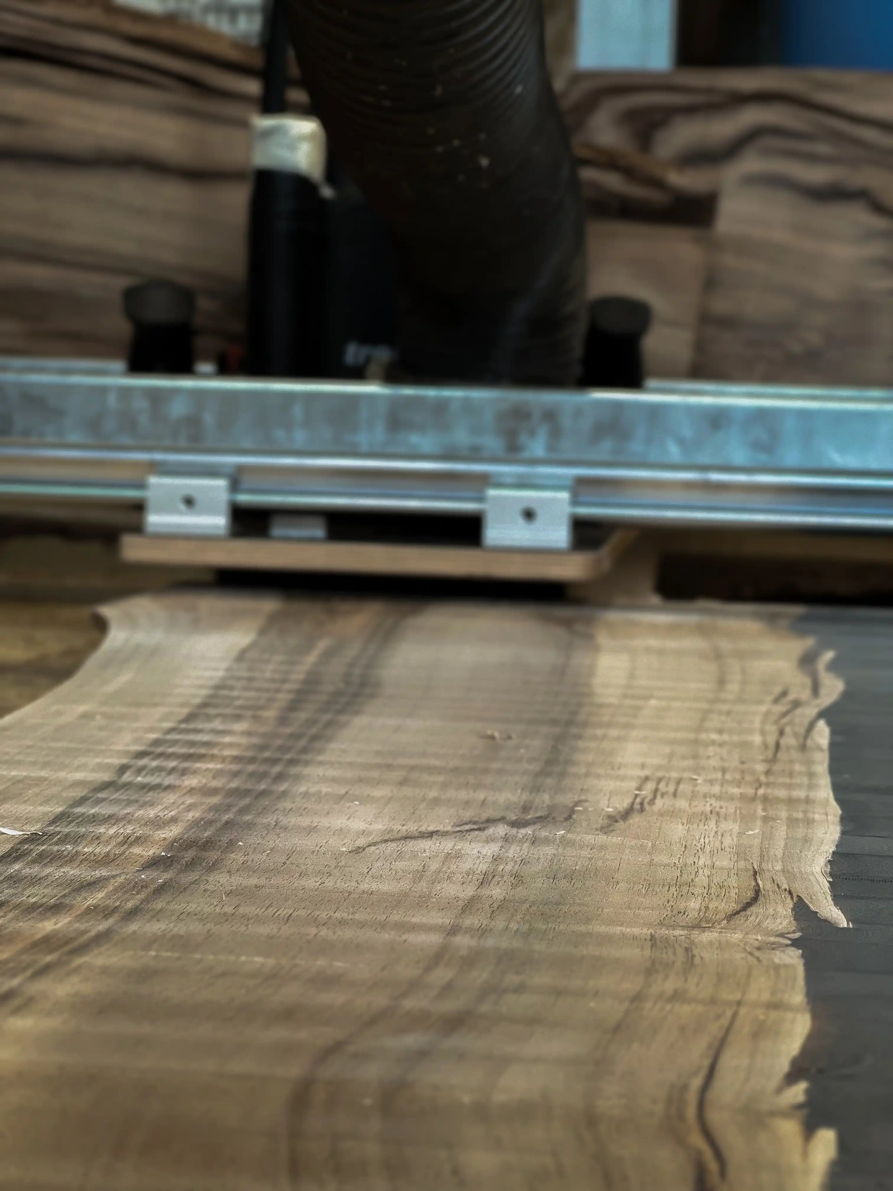
When flattening, small deviations quickly become visible. A deflection in the range of tenths of a millimetre or more can show up across the whole surface as a wave, groove or uneven stock removal. This is especially obvious under raking light, on oiled surfaces or on glossy epoxy resin.
On large wood slabs, every error repeats pass after pass. If the guide gives under load, it's not just one spot that becomes inaccurate – the entire surface follows the wrong plane. That's exactly why stiffness isn't just a technical detail but a directly visible quality factor.
Too little stiffness
The router no longer follows a stable plane. Waves, grooves and visible transitions become more likely.
High stiffness
The guide stays more stable. This makes the cutting depth more even and the surface more repeatable.
Stiffness alone still isn't enough
A stiff design is the foundation, but not the only requirement. The guide also has to be free of play, the flattening bit has to suit the job and the router has to be guided smoothly. A very stiff sled with poor guidance can still produce grooves.
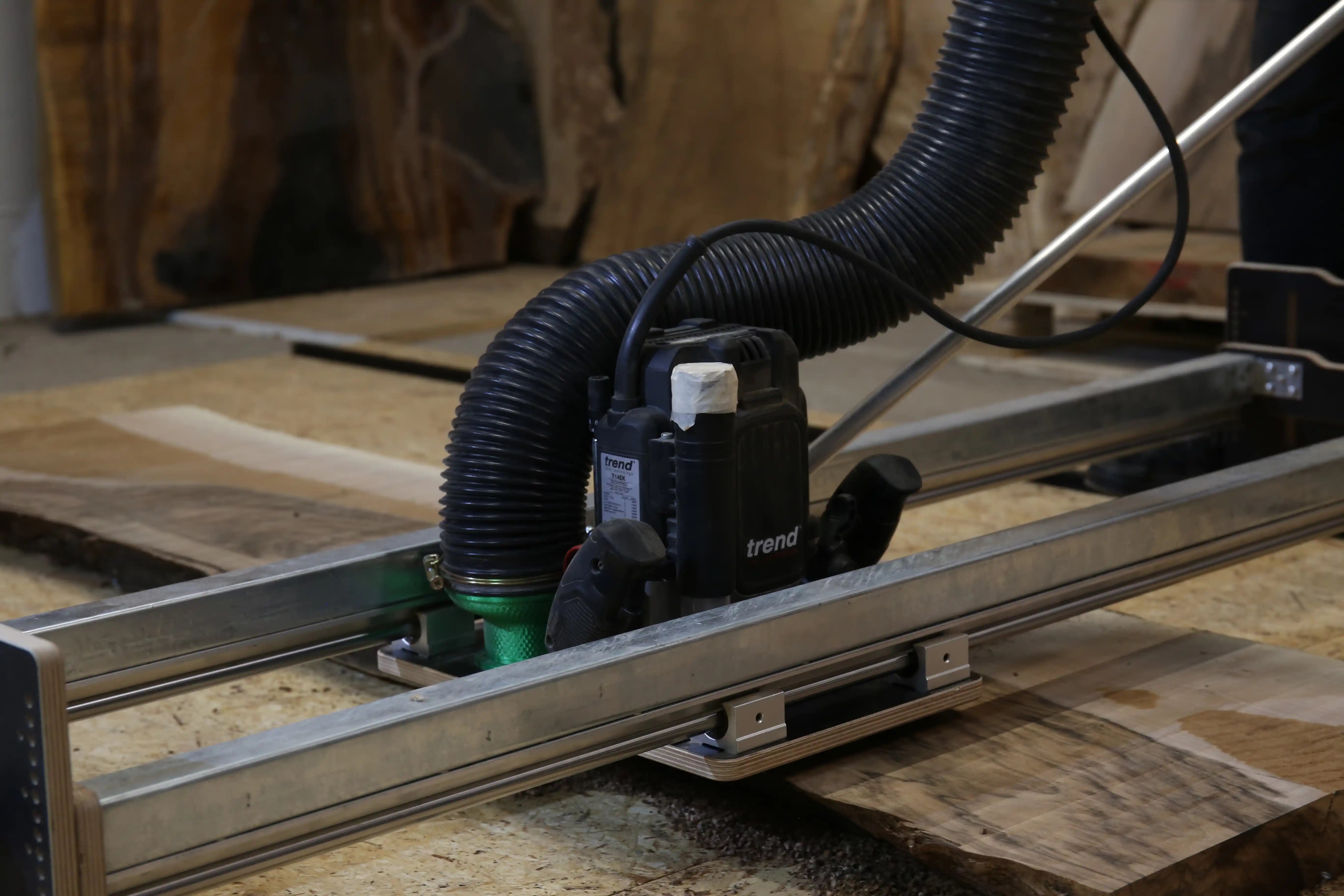
That's why a router sled should always be seen as a complete system: load-bearing structure, linear guide, router plate, push handle, bit, dust extraction and operation all have to work together.
- high bending stiffness of the load-bearing structure
- play-free guidance of the router carriage
- a flattening bit suited to the material and router
- moderate depth of cut instead of maximum stock removal
- calm feed in conventional milling
- clean dust extraction right at the bit
Why the Fräsus Maximus relies on a steel-based design
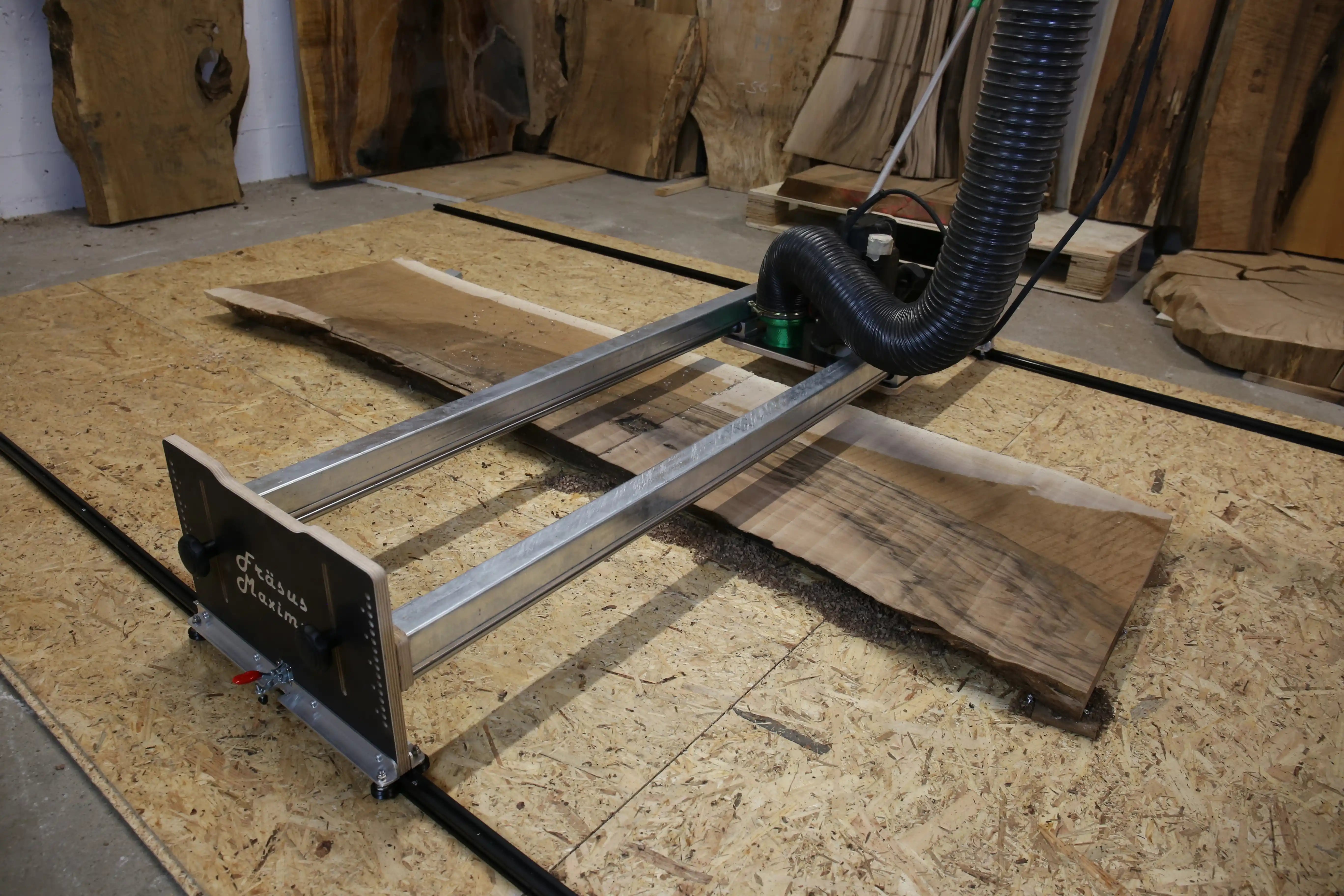
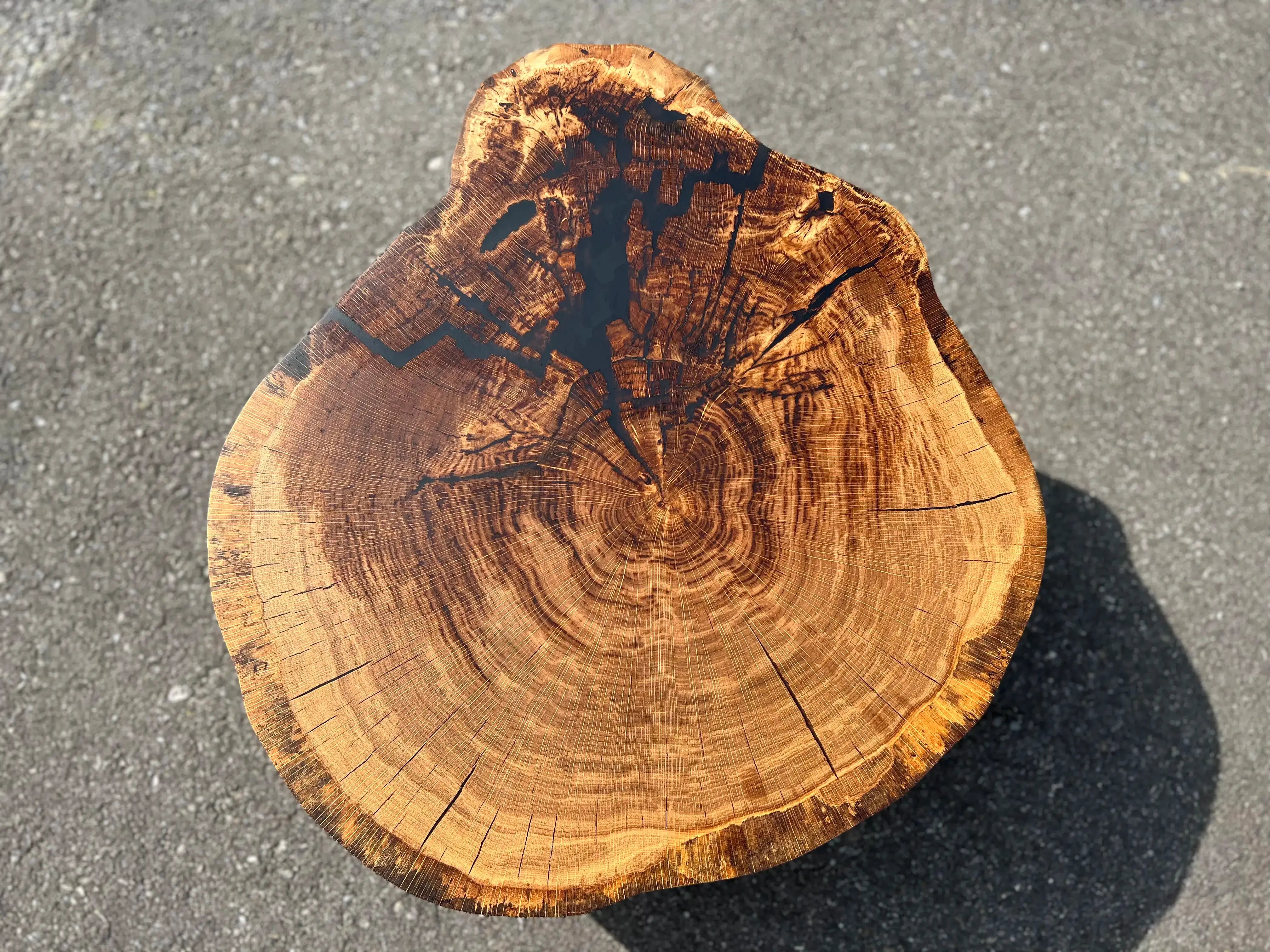
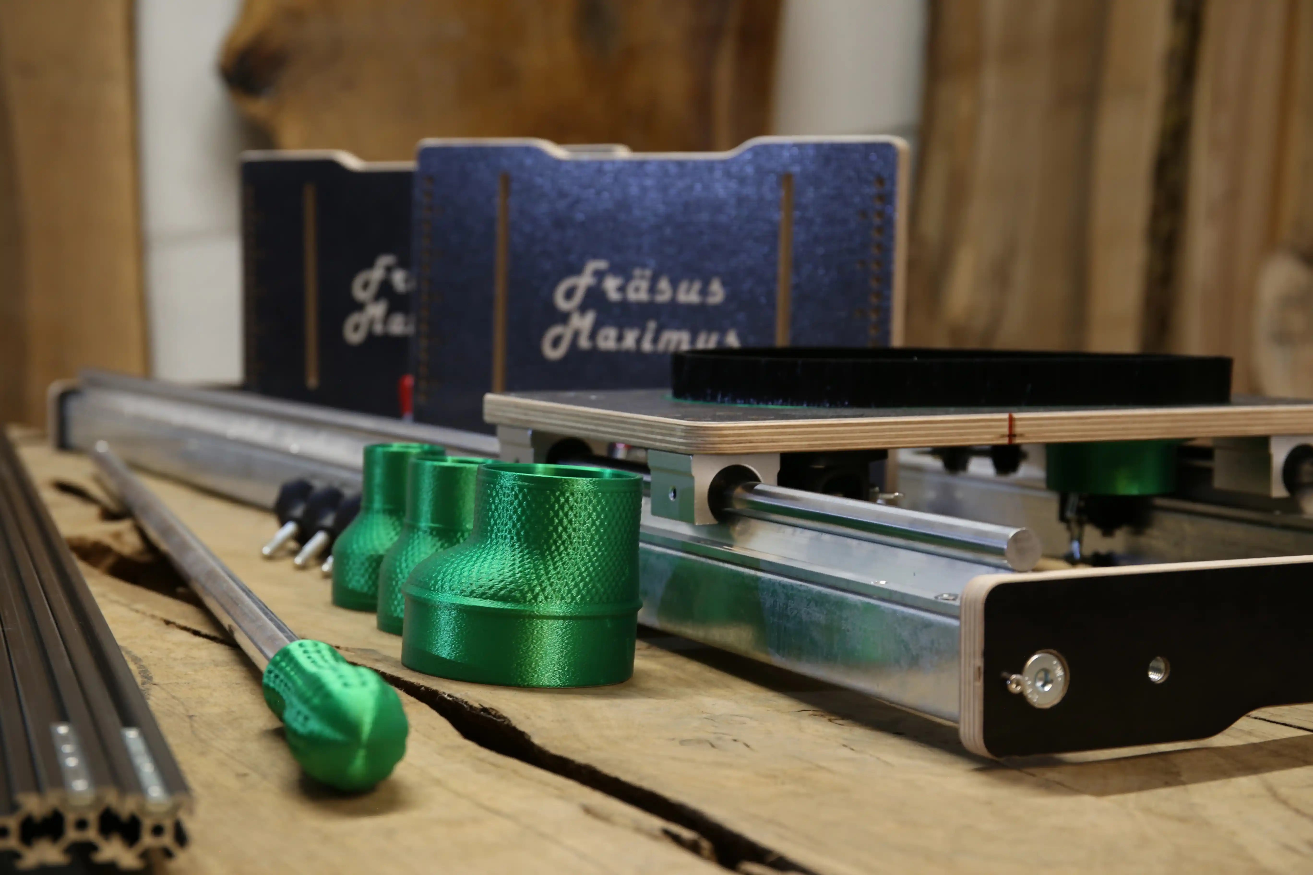
The Fräsus Maximus was developed for large wood slabs, tree slices and epoxy tables. That's why the load-bearing structure deliberately uses steel and a precise guide. The goal isn't the lowest possible weight, but stiff and repeatable guidance of the router.
- solid steel construction for high stiffness
- precise guidance for smooth passes
- suitable for large wood slabs, tree slices and epoxy tables
- operated from the side with push handle and swivel joint
- working area up to approx. 300 × 150 cm
How this differs from the practical article on aluminium vs. steel
This article is the technical deep dive with calculations. If you'd prefer a simpler, practical explanation without formulas, the article “Aluminium or steel for router sleds?” is the better place to start.
For SEO and reader guidance, this split makes sense: the practical article explains the problem in an accessible way, while this technical article shows the mechanical reasoning with numbers.
Internal linking
Link from the practical article to this calculation article using the link text “technical comparison of bending stiffness”. From here, link back to the buying guide and the product page.
FAQ: common questions about bending stiffness
What does bending stiffness mean for a router sled?
Bending stiffness describes how much a guide deforms elastically under load. It's crucial for flattening because any deflection directly affects the cutting depth and therefore the flatness of the surface.
Why is steel stiffer than aluminium?
Steel has a higher modulus of elasticity than aluminium. With the same geometry, steel therefore deforms less under the same load. In the calculation, steel comes out at roughly three times the material factor of aluminium.
Is a 40 × 40 aluminium profile unsuitable for a router sled?
Not in principle. For small workpieces and short spans, an aluminium profile can work. On large wood slabs, tree slices and epoxy tables, however, the lower stiffness can become visible.
Why is the SBR16 guide included in the calculation?
A mounted linear guide can contribute to stiffness structurally because additional material sits further from the neutral axis. This increases the effective second moment of area of the composite cross-section.
Is high bending stiffness alone enough for a flat surface?
No. High bending stiffness is important, but the guide also has to be free of play. In addition, the bit, depth of cut, feed direction and operation all have to fit. Only the complete system produces a truly flat surface.
Conclusion: the calculation explains why steel makes sense for large sleds
The comparison clearly shows that a steel-based design can be significantly stiffer in bending than a typical lightweight aluminium solution of the same or similar size. In particular, the combination of steel tube and mounted linear guide achieves a much higher bending stiffness in this analysis.
Aluminium isn't automatically wrong for small projects. For large wood slabs, tree slices and epoxy tables, however, stiffness quickly becomes the deciding factor. If you want truly flat surfaces, you shouldn't judge a design only by weight or price, but by mechanical stiffness, guide play and real-world load.
Looking for a stiff router sled for large wood slabs?
The Fräsus Maximus was developed for large workpieces – with a steel-based design, precise guidance and controlled operation.

Share:
Aluminium oder Stahl bei Planfräsvorrichtungen?